

Centrifugal Fan Parameters Made Simple: A Practical Guide for 通风机 & 鼓风机 Selection
Centrifugal fan selection often happens with one drawing on the table—but three different “parameter languages” in the room: process engineers focus on duty points, energy managers look for efficiency, and purchasing wants comparable specs. This disconnect frequently leads to equipment that is either oversized, wasting energy, or undersized, causing bottlenecks.
To bridge this gap, we have compiled this comprehensive guide. It aligns the essentials so your 通风机 (ventilation fan) and 鼓风机 (blower) requirements are clear, consistent, and easy to compare, ensuring you select the right equipment for your specific industrial application.


A Shared Vocabulary: The Parameters That Define a 通风机 / 鼓风机
A reliable industrial 通风机 or 鼓风机 specification starts with a complete parameter set—measured under defined gas conditions. Without this precision, even the most advanced fan technology cannot perform optimally.
Airflow (Volume Flow Rate)
Airflow is the lifeblood of any ventilation or process system. It is typically quantified in units such as m³/h, m³/s, or CFM.
However, a raw number is insufficient. You must always clarify whether the airflow is stated for standard air (SCFM, typically at 20°C and sea level) or actual process gas (ACFM). This distinction is critical because industrial processes rarely operate under standard conditions. If temperature, altitude, or gas composition changes the gas density, the fan must be sized to handle the actual volume at the inlet conditions. We recommend correcting pressure and power calculations based on actual density before finalizing any 通风机 and 鼓风机 selection to avoid underperformance.
Pressure: Static vs. Total
Understanding the nuance between static and total pressure is non-negotiable for accurate system design:
- Static Pressure: This is the potential energy that overcomes system resistance caused by ducts, filters, dampers, and equipment.
- Total Pressure: This represents the sum of static pressure and the velocity pressure (kinetic energy) of the gas at the fan outlet.
For industrial blower specifications, mismatching static and total pressure is one of the most common reasons a 通风机 or 鼓风机 fails to meet expectations after commissioning. Always specify which pressure value your system curve is based on.
Speed (RPM), Impeller Design, and Medium Temperature
- Speed: Rotational speed directly influences performance; typically, higher RPM increases pressure and flow but also increases stress on components.
- Impeller Type: The geometry of the impeller determines the achievable pressure range, efficiency, and aerodynamic stability. Different blade angles (forward, backward, radial) serve different purposes.
- Medium Temperature: This is not a footnote. If your gas is hot flue gas (e.g., >200°C), it drastically alters the material selection and bearing cooling requirements. It must be part of the 通风机 parameters and the 鼓风机 parameters from day one.
Power (What Your Motor Actually Needs)
Calculating the shaft power is essential for sizing the motor and VFD correctly. A practical engineering estimate is:
[ P_\text{shaft} \approx \frac{Q \times \Delta P}{\eta_\text{fan}} ]
Where Q is airflow (m³/s), ΔP is total pressure rise (Pa), and η is fan efficiency. However, the installed motor power should also include drivetrain losses (belts, couplings), motor efficiency, and a reasonable safety margin (typically 10-15%) to account for cold starts or minor system fluctuations.
Why “Non‑Flow” Parameters Matter for Long-Term Reliability
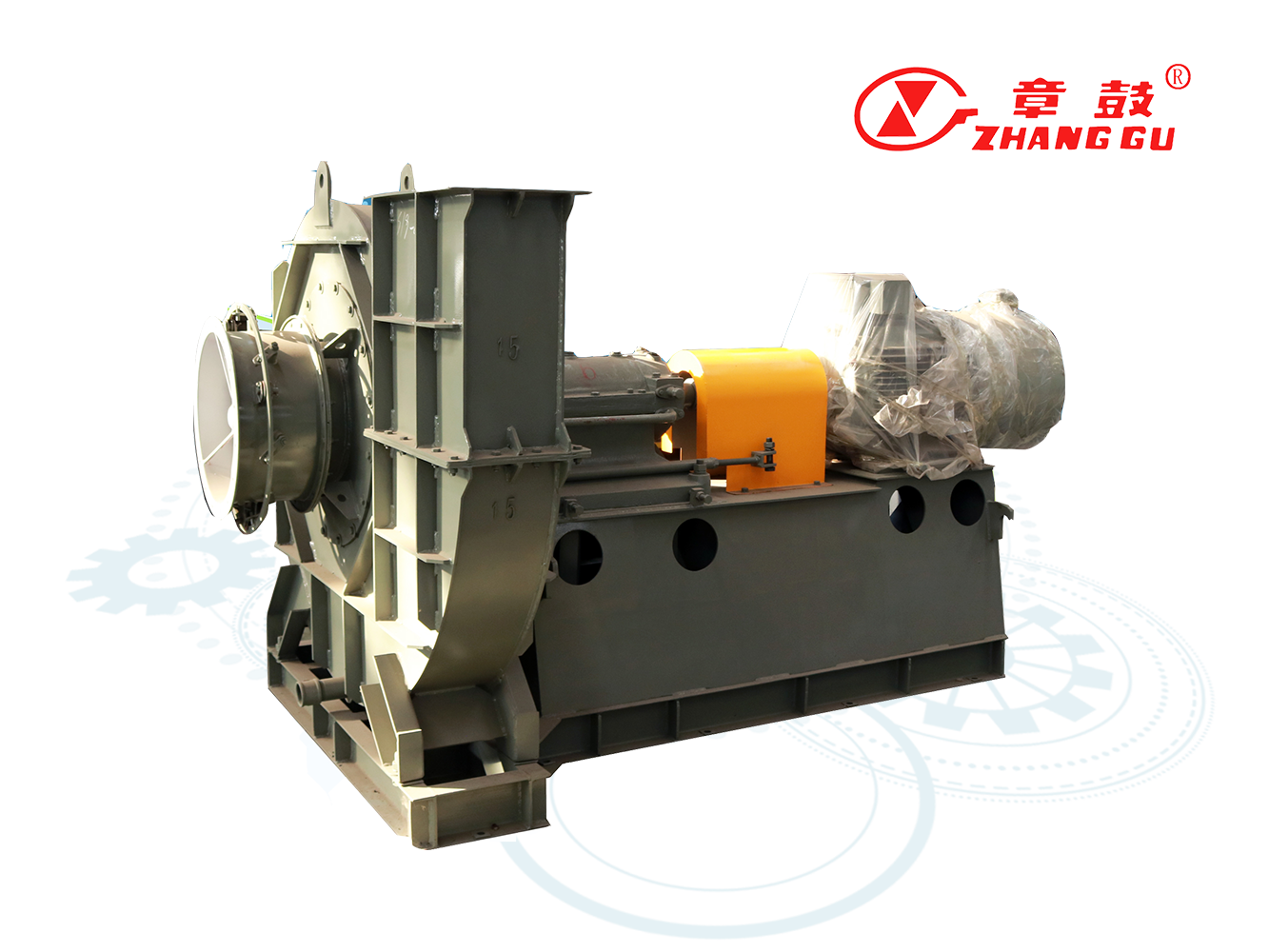
When a 通风机 or 鼓风机 runs 24/7 in a critical process, reliability and operating cost often matter more than the theoretical nameplate performance. At Shandong Zhangqiu Blower Co., Ltd., we prioritize these "hidden" parameters.
- Efficiency: Our SiPESC series high‑efficiency centrifugal fans are a testament to this focus. They reach approximately 91% fan efficiency, meeting national level 1 energy efficiency standards. This translates to significant electrical savings over the machine's lifecycle.
- Vibration Control: High vibration leads to bearing failure and structural fatigue. The SiPESC series adopts a new bearing box structure with imported brand bearings and high-strength steel plates. As a result, vibration is specified at ≤ 2.5 mm/s, supporting stable, low‑maintenance operation even under heavy loads.
- Noise Reduction: A covered casing structure effectively reduces radiated noise. This is particularly useful where ventilation fan rooms are located near personnel areas, improving workplace safety and comfort.
- Sealing & Dust Tolerance: For dusty or hazardous media, the sealing and wear strategy should be written into the 鼓风机 parameters and 通风机 parameters, not negotiated later. We offer specialized sealing solutions to prevent leakage of toxic or corrosive gases.
Matching Parameters to Real Applications (SiPESC vs. High‑Speed)
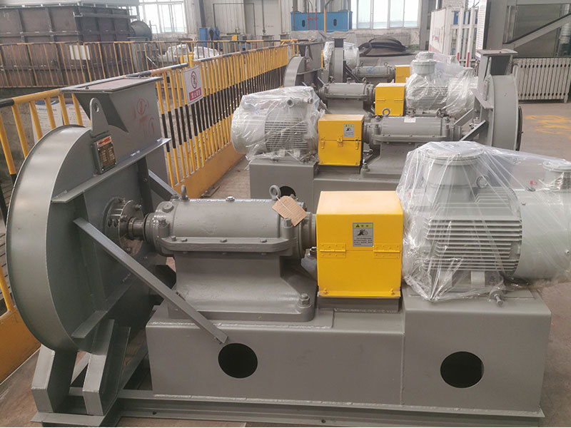
Shandong Zhangqiu Blower Co., Ltd. develops multiple centrifugal fan families so engineers can match a 通风机 or 鼓风机 to actual duty conditions rather than forcing a standard product into a unique application.
SiPESC High‑Efficiency Centrifugal Fans (CFD/CAE Optimized)
These fans are designed on the domestic autonomous CAE software platform SiPESC. We conducted "failure" mechanism analysis and systematic simulation to establish an accurate digital model. By utilizing topology optimization solvers, we refined the fan mechanism to achieve superior aerodynamics.
- Flow Range: 60,000 – 80,000 m³/h
- Total Pressure: 6,000 – 9,500 Pa
- Efficiency: ≈ 91% (Level 1 Energy Efficiency)
- Vibration: ≤ 2.5 mm/s
Practical Benefits: The SiPESC series features a wide high‑efficiency zone and a large flow regulation range. The performance curve is notably flat, meaning the fan maintains stable pressure even if the flow rate fluctuates, making it ideal for systems with variable demand.
High‑Speed Centrifugal Fans with Permanent‑Magnet Direct Drive
Built for compact layouts and high-performance requirements, this series eliminates the transmission losses associated with belt or gearbox drives.
- Speed Range: 3,600 – 6,000 rpm
- Pressure Range: 2.7 – 27 kPa
- Flow Range: 2,000 – 45,000 m³/h
- Fan Efficiency: ≥ 80% across the series
- Motor Efficiency: Up to 98%, with a power factor of ≈ 0.98
- Direct Drive Advantage: With no intermediate transmission, energy savings can exceed 20% compared to conventional arrangements. The compact footprint also simplifies installation in tight spaces.
For applications involving high dust, VOCs, toxic gas, or requiring special process sealing, we extend the base 通风机 and 鼓风机 parameters with dedicated product solutions such as special‑seal induced draft fans.
How to Read a Fan Performance Curve (The Decision-Making Sequence)
Most centrifugal fan curves plot flow vs. pressure at a fixed speed, with overlaid curves for efficiency and power. Understanding this chart is the key to selecting a fan that operates in its "sweet spot."

- Define the Duty Point: Identify your required airflow and required static/total pressure based on process needs.
- Overlay Your System Curve: Remember that system resistance typically rises roughly with the square of the flow rate (Q²). Plotting this helps visualize how the system reacts to flow changes.
- Locate the Operating Point: This is the intersection of the fan performance curve and your system resistance curve. This is where the fan will actually run.
- Read Efficiency and Power: At the operating point, look at the efficiency contours. Ideally, your point should fall within the "efficiency island" (the peak efficiency zone). Also, read the power requirement to verify motor margin.
- Check Control Strategy: If using a Variable Frequency Drive (VFD), apply affinity laws (Q ∝ N, ΔP ∝ N², P ∝ N³) to simulate performance at different speeds. This ensures the fan remains stable across the entire control range.
Industry guidance on interpreting curves is consistent with this workflow, as seen in standards from organizations like AMCA.
A Practical RFQ Template (Keeps 通风机 / 鼓风机 Specs Comparable)
To ensure you receive accurate and comparable quotes from suppliers, use one consistent table format. This avoids ambiguity and ensures all vendors are bidding on the same requirements.
| Item | Requirement (fill in) |
|---|---|
| Flow (m³/h) | Min / Normal / Max |
| Pressure Basis | Static or Total (Pa) |
| Gas/Medium | Air / Flue Gas / Process Gas |
| Medium Temperature (°C) | Normal / Peak |
| Dust Content | Concentration + Particle Notes |
| Speed/Control | Fixed Speed / VFD Range |
| Efficiency Target | Requested (%) or Energy Grade |
| Noise Limit | dB(A) at Distance/Condition |
| Vibration Limit | mm/s (e.g., ≤ 2.5 mm/s) |
| Sealing | Standard / Special Seal |
Common Selection Mistakes (And How to Avoid Them)
Even experienced engineers can fall into traps during the selection process. Here are a few to watch out for:
- Mixing Static and Total Pressure: Comparing a quote based on static pressure with one based on total pressure is apples-to-oranges. Always clarify the basis.
- Selecting the Curve Extreme: Do not select a fan where the duty point sits at the far right (choke) or far left (surge) of the curve. Aim for the center, high-efficiency band.
- Ignoring Future Resistance Growth: Filters load up, and ducts get modified. If you don't account for this extra resistance, your operating point will shift, potentially reducing flow below required levels.
- Treating Dust and Sealing as “Later”: For industrial service, these features determine the lifespan of the unit. They must be part of the 鼓风机 parameters and 通风机 parameters up front to ensure the correct impeller and seal types are selected.
Next Step: Share Your Duty Point for a Fast, Accurate Selection
Selecting the right fan doesn't have to be a guessing game. If you provide airflow, pressure basis (static/total), medium temperature, and dust/gas details, our engineering team can recommend a suitable 通风机 / 鼓风机 family—whether it's our ultra-efficient SiPESC series, our compact High-Speed permanent magnet series, or a custom wear-resistant solution.
We will confirm the operating point on the fan performance curve to ensure reliability and efficiency from day one.
Contact our team for selection support and a quotation.
References
- Air Movement and Control Association International. (n.d.). Straightening out fan curves. https://www.amca.org/educate/articles-and-technical-papers/amca-inmotion-articles/straightening-out-fan-curves.html
- New York Blower Company. (2024, May 7). How do fan curves work? https://www.nyb.com/latest-news/2024/05/07/how-do-fan-curves-work/
- Stanmech. (n.d.). How to interpret a blower/fan curve. https://www.stanmech.com/articles/how-to-interpret-a-blowerfan-curve


